
Internet of Moving Things ebook
Mouser ElectronicsWelcome from the Editor
The 1939–40 New York World’s Fair was the first of its kind to feature the future, with exhibits from around the world that allowed visitors to look at “the world of tomorrow.” At that Fair, more than 44 million people attended one particularly influential exhibit and ride: Norman Bel Geddes’ Futurama, which prophesized an American utopia with streamlined vehicles, cutting-edge technologies, and a built environment that would ultimately reform society.
Over the past 70 years, we’ve seen in hindsight that Bel Geddes’ masterpiece may not have gotten every detail correct. The advances haven’t come as quickly as Geddes thought, of course; by the 1960s, ads were still touting driverless cars of the future, and it’s only been recently that autonomous vehicles have begun testing in various areas.
However, Bel Geddes Futurama display illustrated what we still aim to do: Harness the technologies and ideas we have today to present a “new and clearer view of today in preparation for tomorrow.” In this eBook, we put autonomous vehicles smackdab in the middle of connected infrastructure and emphasize the Internet of Moving Things — where IoT meets mobility — because this intersection poses some of the most demanding and interesting design challenges.
Think of all of the solutions we design… To store, analyze, and gain insights from big data; to govern technologies and develop standards; to provide speed, security, privacy, and ease-of-use; to accommodate a plethora of data formats, devices, and populations; to make urban living more efficient, cost-effective, and more environmentally friendly; and to keep up with a continuously-changing technological landscape. Well, these solutions will soon be on the move, zipping along in a streamlined, tailored, and self-driving vehicle; connecting to other vehicles, infrastructure, and people; and changing the way people work and live.
Many visionaries since that fateful World’s Fair have demonstrated that streamlined, tailored, autonomous vehicles at the center of a built environment will ultimately reform life and work as we’ve known it. With the ingenuity and courage of those who came before us — and who currently work with us — we’ve made significant headway. In what ways will technologies continue to evolve to reach this dream? That’s up to you.
Norman Bel Geddes will be proud.
Deborah S. Ray
Editor, Mouser Electronics
Download and read the full ebook below.

Achieving Optimum Radio Range (Rev. A)
Texas Instruments
Introduction to Magnetic Resonance Imaging (MRI)
Texas InstrumentsMagnetic Resonance Imaging is a non-invasive diagnostic technology that produces anatomical images. Unlike computed tomography (CT), MRI does not carry the risk of ionizing radiation exposure. The MRI system shown in this application note uses a superconducting magnet to align hydrogen atoms in the body; then excites the atoms with radio frequency (RF) energy from the transmitting RF coil. As the atoms return to equilibrium, energy is released in the form of radio waves which are recorded by the receiving RF coil. The rate at which the atoms return to equilibrium, as well as the energy released, is determined by the location and chemical makeup of the surrounding material. This information is processed to create images of the tissues present in the body.

SimpleLink Wi-Fi Enabled Electronic Smart Lock
Texas InstrumentsThis application report describes the development of Wi-Fi enabled electronic smart locks (e-locks). Specifically, the benefits of adding Wi-Fi to an e-lock design are examined.
Different Wi-Fi use cases are presented along with an estimate of system battery life for two main use cases. This application report demonstrates that SimpleLink Wi-Fi makes it possible to create a battery powered e-lock design that can be securely monitored and controlled from the cloud.

Simplifying 4K SDI Video Design with a Bidirectional I/O
Texas InstrumentsIn 4K serial digital interface (SDI) video designs, flexibility, scalability, and cost savings are essential to maximize design reuse and develop an extensive 12G-SDI portfolio. A bidirectional input/output (I/O) addresses these critical needs. This application note explains how the features and diagnostic tools of the LMH1297 12G-SDI bidirectional I/O enable various SDI design benefits. This application note also provides several application examples where the LMH1297's versatility simplifies 4K video design.

Spurs Analysis in the RF Sampling ADC
Texas Instruments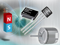
Angle Measurements With Linear Hall Effect Sensors
Texas InstrumentsThis application report discusses how linear Hall effect sensors can be used to measure 2D angles, including both limited-angle and 360° rotation measurements. This report provides details on some calibrated and uncalibrated implementations to help meet angle measurement accuracy requirements. This report also covers the number of sensors needed, and the preferred magnet types for each method.

Practical Thermal Design With DC/DC Power Modules
Texas InstrumentsAll DC/DC converters dissipate power in the form of heat. This heat has to be managed properly so that the converter maintains operation within the recommended temperature limits. Usually, the copper on the printed circuit board (PCB) is utilized to help dissipate the heat. This application note outlines a design procedure to quickly estimate the minimum required copper area on the PCB for a successful thermal design with DC/DC power modules.

Designing Connected CPAP Machines With SimpleLinkTM Wi-Fi® Wireless MCU
Texas Instruments_.png)
Understanding Smart Gate Drive (Rev. C)
Texas InstrumentsThe gate driver in a motor system design is an integrated circuit (IC) that primarily deals with enhancing external power MOSFETs to drive current to a electric motor. The gate driver acts as an intermediate stage between the logic-level control inputs and the power MOSFETs. The gate driver must be robust and flexible enough to accommodate a wide variety of external MOSFET selections and external system conditions.
Texas Instrument’s Smart Gate Drive provides an intelligent solution for driving and protecting the external power MOSFETs. This feature lets system designers adjust the MOSFET slew rate, optimize switching and EMI performance, decrease bill of materials (BOM) count, automatically generate dead-time, and provide additional protection for the external power MOSFETs and motor system.
This application report describes the theory and methods behind enhancing a power MOSFET, how the IDRIVE and TDRIVE features are implemented in TI Smart Gate Drivers, and details many of the systemlevel benefits.

System power architectures in body control modules
Texas InstrumentsFunctions of comfort and convenience available in all modern vehicles today (and in the foreseeable future) rely on body control modules (BCMs). BCMs work behind the scenes to operate headlights, rear lights, interior ambient lights, windshield wipers and more.
Both the quantity of BCMs in a car and the number of comfort and convenience loads that each BCM controls vary across vehicle models. From a BCM that only handles lighting functions to a BCM that includes gateway functionality and car-access support, the number of BCMs and their complexity depend on the underlying architecture of the vehicle body electronics.
BCM designs are also rapidly evolving. For example, junction boxes (also known as power distribution boxes), which distribute power to various loads using relays, are either being integrated into BCMs or converted to BCM-like modules to distribute power through semiconductor switches. More driver inputs and sensors are being connected to BCMs as the number of comfort and convenience features increases. And as the number of dedicated load-control modules (such as those for roof motor control) increases, BCM networking requirements also increase.
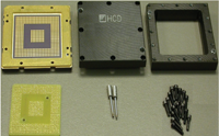
AC275: Actel CCGA to FBGA Adapter Socket Instructions
MicrosemiMicrosemi SoC Products Group recently introduced RTAX-S/L, the next generation designed-for-space antifuse field programmable gate arrays (FPGAs). RTAX-S/L, with up to four million system gates, is SoC Products Group's highest density family, providing the space designer with nearly 250 k ASIC gates and error correction and detection (EDAC) protected static RAM. RTAX-S/L is the first SoC Products Group family designed for use in the ceramic column grid array (CCGA) package configuration. SoC Products Group has developed a low cost prototyping methodology for RTAX-S/L using the Axcelerator family of FPGAs.
AN-931 - Understanding PulSAR ADC Support Circuitry
Analog Devices Inc.Successive approximation register (SAR) analog-to-digital converters (ADCs) use various new techniques for improved resolution. Understanding how these devices work is important in preventing malfunction and erroneous issues. This application note discusses in general the pitfalls that occur regularly when using SAR ADCs and, more importantly, how to easily prevent them.
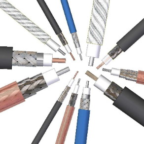
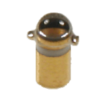
ANE016 - Coaxial cables and cable assemblies
Wurth ElektronikThe function of a coaxial cable is to deliver a RF signal from point A to point B through various connector interfaces. Würth Elektronik offers a wide range of quality cable assemblies. This application note is based on Würth Elektronik standard cable types and helps to understand which points to consider when selecting a cable for custom tailored cable assemblies.
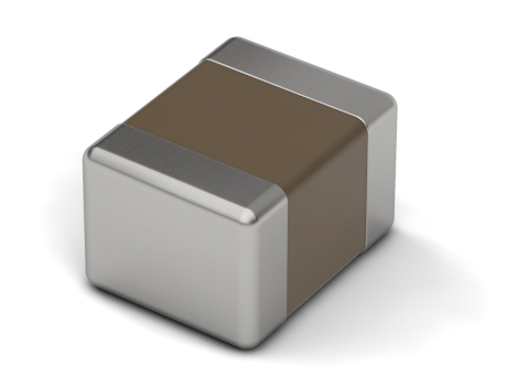
ANP098 - Effect of layout, vias and design on the blocking quality of filter capacitors
Wurth ElektronikBlocking capacitors on supply pins basically have the task of locally short-circuiting the clocked current loop of the digital circuits using a low impedance. This reduces the radiated magnetic field strength and the RF interference currents coupled into the supply voltage level as much as possible. If the capacitors are optimally selected with regard to their impedance curve and geometrically optimally placed at the VCC pins, then the clocked RF current can be blocked in the best possible way.
The technical literature offers extensive theoretical information on correct PCB layout techniques and multi-stage filter & blocking capacitors for supply pins of digital ICs. However, there is often a lack of real measurements or practical simulations. The goal of this AppNote is to show the influence of the MLCC design, the number of ground vias and the placement of the filter components to each other. In addition, it is shown that one can get into unexpected problems with an unfortunate dimensioning of capacitor banks.
To show the various influences in practice, using a four-layer PCB designed exactly for an impedance of 50 Ω, the insertion loss S21 was measured over a wide frequency range from 300 kHz to 3 GHz. Two simulations with the freeware tool LTSpice and the professional tool EMCoS support the observation and show how close one can get to the real measurement using E5071C (ENA RF Network Analyzer) and which influence the via positioning has relative to each other. MMCX types from Würth Elektronik eiSos were used as RF connectors.
Content:
- Circuit diagram and measurement setup
- PCB layout in detail
- LTSpice and EMCoS simulation
- Simulations- & measurement results
App-Note-200 - Thermal Behaviour of GaAs LEDs
TT electronics plcThe output power (P0) of a GaAs LED is a function of forward current (IF). As this forward current increases, the output power will also increase. This forward current flowing through the LED generates heat (P0) which causes the junction temperature (ƟI) of the diode to increase. As the junction temperature increases, the output power decreases.
AN-202 - An IC Amplifier User’s Guide to Decoupling, Grounding, and Making Things Go Right for a Change
Analog Devices Inc.An IC Amplifier User’s Guide to Decoupling, Grounding, and Making Things Go Right for a Change
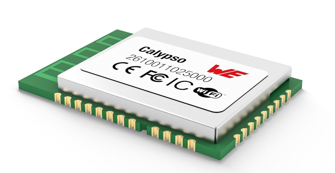
ANR028 - UART-to-Wi-Fi brigde using Calypso
Wurth ElektronikThis application note describes a special function of the Calypso, the transparent mode. The most common use-case for this mode is a serial cable replacement. The Calypso can be configured in a way, that data transmitted to it via UART are converted into IP messages and exchanged with a receiver in form of a TCP server, TCP client or UDP endpoint.
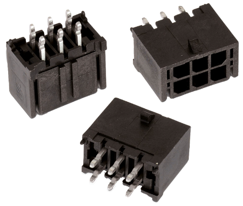
ANE001 - Low Force Crimp Contacts
Wurth ElektronikAlthough they are really designed for permanent connection, plug connectors with crimp contacts have to be disconnected every so often. To avoid this becoming a trial of strength for the maintenance technician who then damages the plug connector, Würth Elektronik eiSos developed an alternative with reduced insertion and pulling force.
Manufacturers of household electrical appliances have to take servicing into consideration, even in the development of their products. This means that components prone to wear and defects, such as the brewing unit of a coffee machine, have to be easily accessible. It is even more important to use components that are not damaged for the first time by the repair and are therefore sure to cause follow-on costs.
Crimp plug connectors with more than 10 pins are examples of such components. Equipped with standard contacts, they can only be disconnected with great difficulty; with 24 pins they are almost impossible to disconnect. Given an installation situation which is complicated to access, smaller numbers of pins are enough to hamper disconnection of the wire-to-board connection. Because, in these place in particular, it is impossible to use tools, there is only one solution: to tug on the cable! And to mechanically damaged the plug connector in the process.
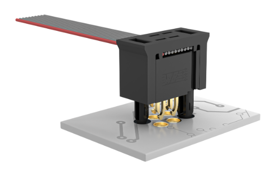
ANE004 - REDFIT IDC SKEDD – Debugging & Firmware-Upload
Wurth ElektronikThe connection between the debugger and the microcontroller is crucial in development to load firmware, check the code and find errors. But also in the production of small and medium series this connection is used to load the firmware after assembly. Usually a socket is soldered to the board to connect the debugger. This socket is usually only used once, costs space, height and money. Not only money that we pay for the component, but also for the procurement logistics and the assembly. But an initial connection is necessary to get the firmware (FW) into the microcontroller. For large series, microcontrollers are recorded before assembly. However, this is only profitable with high quantities. Würth Elektronik now offers a solution also for smaller series.


