ANR032 - Adrastea Cloud Connectivity
Wurth ElektronikThe Internet of Things (IoT) can be broadly defined as an umbrella term for a range of technologies that enable devices to connect and interact with each other. Interacting devices generating data provide the foundation for a range of new applications. Industrial automation, healthcare, smart home, smart cities, smart grids and smart farming are some of the areas in which IoT provides substantial benefits.
Dubbed the "fourth industrial revolution" or Industry 4.0, the Industrial IoT (IIoT) is the digitization of industrial assets and processes that connects products, machines, services, locations/ sites to workers, managers, suppliers, and partners. Closer networking of the digital world with the physical world of machines helps achieve higher productivity, safety, efficiency and sustainability.
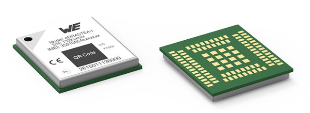
The core task of any IoT solution is to get data from the field to the cloud where analysis of the same generates the desired value addition for the application. This application note aims to propose an elegant solution to achieve this task based on Adrastea-I Cellular module.
ANP116 - Gigabit Ethernet interface from an EMC perspective
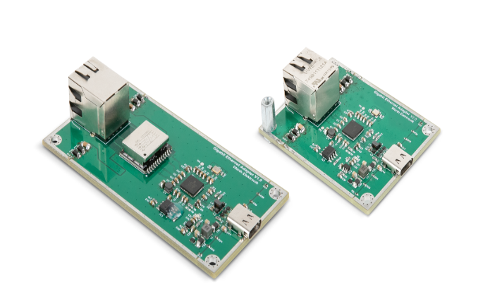
Wurth ElektronikGigabit Ethernet has established itself as the standard in the networking in office and industrial environments. However, when designing a Gigabit Ethernet interface, questions often arise about the shield connection of the cable and the design of the front end, especially with regard to the ground connections. Searches on the Internet reveal various suggestions for shield termination, often suggesting a 1-nF Y capacitor. However, the effect on the performance of the interface and the EMC behavior is not described. Würth Elektronik has therefore developed a reference design to be able to measure EMC aspects in detail. This App Note is based on the reference design and takes a detailed look at the EMC behavior of the Gigabit Ethernet interface with different shield connections and configurations. In addition, the App Note provides design recommendations based on extensive hardware testing.
Contents:
- Gigabit Ethernet basics
- Measurements in the time domain
- EMC evaluation of the reference design
Disturbance variables
Interference emission
Interference immunity - Conclusion and design recommendations
ANM005 - Using multiple sensors on single I²C bus
Wurth ElektronikMEMS sensors have primarily digital interfaces. The I²C bus is one of these interfaces, which also support a bus system. Different sensors, which typically have a different I²C address, can thus be easily addressed individually via this bus. However, it becomes challenging when several sensors with identical I²C addresses are to be operated on one bus. This document shows different solutions how to build up a bus system nevertheless.
ANE015 - Inrush current for connectors
Wurth ElektronikElectric motors request high starting current. Capacitors could have high discharge current. Certain type of lightening and many more examples request high current during a short time. Would you need to design your connector on this inrush current that is use for a short period of time or save money and space with a connector that simply respect stable current ?
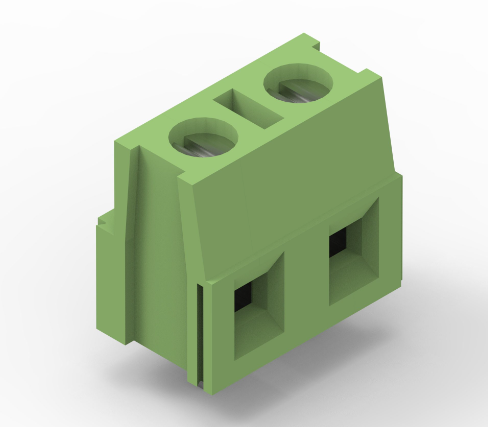
You will learn how to use inrush currents that exceed working ones, up to 16 times on terminal blocks.
ANR030 - Custom Firmware development using Nordic nRF Connect SDK
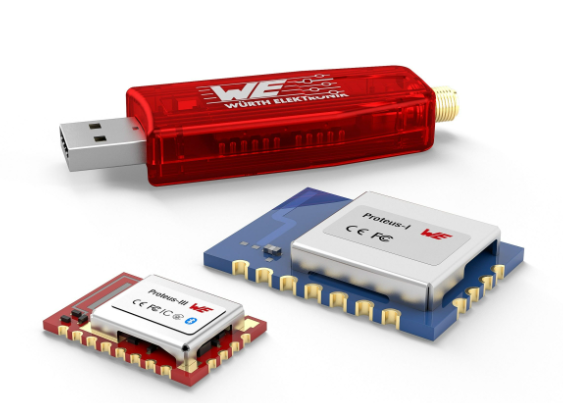
Wurth ElektronikThis application note gives a short overview about the options to create a custom firmware for Würth Elektronik eiSos radio modules by using the hardware platform and the embedded nRF5x system on chip. It presents options on firmware development environments and accessories (like SDKs) for the use within the nRF5 ecosystem.
The reader is informed on how to access to a multitude of radio standards (like Bluetooth Low Energy, Bluetooth MESH, Bluetooth LE Audio, Matter, Zigbee, Thread, Wirepas) for custom firmware developments whilst the hardware plattform can stay the same.
ANR029 - Remote GPIO Control
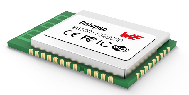
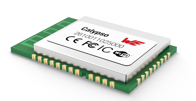
Wurth ElektronikThe Calypso module offers four remote controllable GPIOs. This Pins can be configured as input, output high/low and some of them as PWM. This provides the possibility to perform simple and quick hostless operation. This application note describes how to use and configure this functionality.
ANE012 - Coaxial PCB Connector - PCB-Transmission Line Design Guide
Wurth ElektronikThe function of a RF (Radio Frequency) transmission line is a directing RF signal from a source to a load with minimal loss and distortion. Impedance plays an important role in signal transmission. Even if the trace impedance already matches, adding a connector can cause an impedance mismatch and thus signal distortions due to reflections. The purpose of this application note is to outline methods for improving signal transmission when a connector is added on a PCB.
ANP121 - Filter and surge protection for I2C Bus
Wurth ElektronikThe I²C bus (Inter-Integrated Circuit) is a popular serial communication interface. It is mainly used to connect microcontrollers with peripheral ICs (e.g. sensors or memory). The bus uses one bidirectional data line (SCL) and one clock line (SDA) each. However, the I²C bus is not only used within circuit boards, but is also extended into other areas in many applications with the aid of various connectors and cables. This makes the I²C bus potentially more susceptible to external interference such as ESD, burst and radiated RF disturbances. The goal of this application note is to show the reader a suitable filter and protection circuit that increases the noise immunity of the I²C bus without sacrificing the signal quality of the data and clock lines. For this purpose, simulation models were created in LTspice and a real application was measured to verify the simulation results.
Contents:
• Basics and specifications I2C bus
• Selection of filter and overvoltage protection components
• Simulation with LTspice for a clock frequency of 400 kHz
• Measurement of a real application with a clock frequency of 400 kHz
ANP006 - Influence of Control Loop by an Output Filter
Wurth ElektronikThe output voltage of switching regulators has a voltage ripple that can disturb with electrical power supplied circuits and lead to electromagnetic disturbances. Thus output filters are often used for noise suppression, which may under certain circumstances have an influence on the control loop. To prevent output power losses it may be necessary to compensate the control loop.
No matter what switching regulator topology is used, as a result of the parasitic series resistor ESR and the parasitic inductance ESL of the output capacitor, the output current causes an undesired residual ripple. Depending on the capacitor type selected, a relatively large residual ripple is created, which has varying wave forms. A common electrolytic capacitor, for example, can have a ripple voltage of up to a few hundred millivolt, depending on the output power of the switching regulator. If a ceramic capacitor is chosen, the ripple voltage may only be a few tenth of a Volt.
ANP109 - Impedance Spectra of Different Capacitor Technologies
Wurth ElektronikImpedance and capacitance spectra (or scattering parameters) are common representations of frequency dependent electrical properties of capacitors. The interpretation of such spectra provides a wide range of electrochemical, physical and technical relevant information. Those need to be separated from the ever-present measurement artifacts as well as parasitic effects.
Since it is sometimes not possible to provide all data in the data sheet, the engineer may have to utilize measured spectra to choose the suitable component for the circuit design. To provide the best possible database, Würth Elektronik eiSos has implemented the online tool REDEXPERT, where spectra and other measurements are provided.
In this note, we will recap the properties of such spectra and discuss how basic electrical characteristics can be inferred from it.
ANE008 - Hot plugging of PoE Modular Jacks
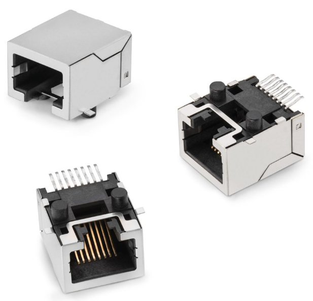
Wurth ElektronikModular jacks (MJ) connectors and cables are broadly used to bring Ethernet signal up to 10 Gb/s depending on the category of the product. It is also possible to deliver power through it with PoE. Type 1 and 2 PoE specifications are applicable to Würth Elektronik modular jacks. In this Application Note we will study if recommendations can be extended up to Type 4. Moreover most WE MJ connectors are rated up to 1.5 A. That is why they will be tested at this current.
However, like all of the other types of input/output connectors, MJ connectors should not be plugged and unplugged (hot swapped) under load. Disconnectors products (breakers, switch, etc.) have special disconnection areas to be able to break the electric arc without damaging the contacts. This Application Note will show the capabilities of modular jacks in case they are accidently used as a disconnector product in a PoE application
ANE018 - Plastic Material Properties
Wurth ElektronikIt has been observed that the natural color of halogen-free polyamide (PA) plastic used in Würth Elektronik connectors turns brown during the SMT process (Reflow soldering). The aim of this technical note is to understand this phenomenon and demonstrate whether and how it may impact the plastic material properties of our connectors. This was achieved by conducting spectroscopy IR and differential scanning calorimetry tests.
ANE016 - Coaxial cables and cable assemblies
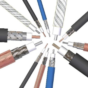
Wurth ElektronikThe function of a coaxial cable is to deliver a RF signal from point A to point B through various connector interfaces. Würth Elektronik offers a wide range of quality cable assemblies. This application note is based on Würth Elektronik standard cable types and helps to understand which points to consider when selecting a cable for custom tailored cable assemblies.
ANP098 - Effect of layout, vias and design on the blocking quality of filter capacitors
Wurth ElektronikBlocking capacitors on supply pins basically have the task of locally short-circuiting the clocked current loop of the digital circuits using a low impedance. This reduces the radiated magnetic field strength and the RF interference currents coupled into the supply voltage level as much as possible. If the capacitors are optimally selected with regard to their impedance curve and geometrically optimally placed at the VCC pins, then the clocked RF current can be blocked in the best possible way.
The technical literature offers extensive theoretical information on correct PCB layout techniques and multi-stage filter & blocking capacitors for supply pins of digital ICs. However, there is often a lack of real measurements or practical simulations. The goal of this AppNote is to show the influence of the MLCC design, the number of ground vias and the placement of the filter components to each other. In addition, it is shown that one can get into unexpected problems with an unfortunate dimensioning of capacitor banks.
To show the various influences in practice, using a four-layer PCB designed exactly for an impedance of 50 Ω, the insertion loss S21 was measured over a wide frequency range from 300 kHz to 3 GHz. Two simulations with the freeware tool LTSpice and the professional tool EMCoS support the observation and show how close one can get to the real measurement using E5071C (ENA RF Network Analyzer) and which influence the via positioning has relative to each other. MMCX types from Würth Elektronik eiSos were used as RF connectors.
Content:
- Circuit diagram and measurement setup
- PCB layout in detail
- LTSpice and EMCoS simulation
- Simulations- & measurement results
ANR028 - UART-to-Wi-Fi brigde using Calypso
Wurth ElektronikThis application note describes a special function of the Calypso, the transparent mode. The most common use-case for this mode is a serial cable replacement. The Calypso can be configured in a way, that data transmitted to it via UART are converted into IP messages and exchanged with a receiver in form of a TCP server, TCP client or UDP endpoint.
ANE001 - Low Force Crimp Contacts
Wurth ElektronikAlthough they are really designed for permanent connection, plug connectors with crimp contacts have to be disconnected every so often. To avoid this becoming a trial of strength for the maintenance technician who then damages the plug connector, Würth Elektronik eiSos developed an alternative with reduced insertion and pulling force.
Manufacturers of household electrical appliances have to take servicing into consideration, even in the development of their products. This means that components prone to wear and defects, such as the brewing unit of a coffee machine, have to be easily accessible. It is even more important to use components that are not damaged for the first time by the repair and are therefore sure to cause follow-on costs.
Crimp plug connectors with more than 10 pins are examples of such components. Equipped with standard contacts, they can only be disconnected with great difficulty; with 24 pins they are almost impossible to disconnect. Given an installation situation which is complicated to access, smaller numbers of pins are enough to hamper disconnection of the wire-to-board connection. Because, in these place in particular, it is impossible to use tools, there is only one solution: to tug on the cable! And to mechanically damaged the plug connector in the process.
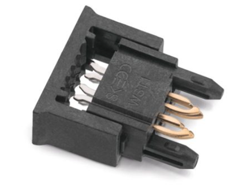
ANE004 - REDFIT IDC SKEDD – Debugging & Firmware-Upload
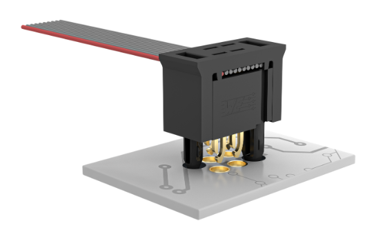
Wurth ElektronikThe connection between the debugger and the microcontroller is crucial in development to load firmware, check the code and find errors. But also in the production of small and medium series this connection is used to load the firmware after assembly. Usually a socket is soldered to the board to connect the debugger. This socket is usually only used once, costs space, height and money. Not only money that we pay for the component, but also for the procurement logistics and the assembly. But an initial connection is necessary to get the firmware (FW) into the microcontroller. For large series, microcontrollers are recorded before assembly. However, this is only profitable with high quantities. Würth Elektronik now offers a solution also for smaller series.
ANE006 - Derating of Connectors
Wurth ElektronikWe know that electrical resistance creates heat when a current goes through it. The amount of heat is directly related to these two parameters. Electrical connectors always specify a working current which is defined by international, national or even industry specific standards that provide a maximum temperature rise (∆t) value allowed under working current. These are measured at the hottest point of the connector by using a very precise processes (usually EIA364-70 standard is followed). Different standards might allow different values for this maximum ∆t. For UL certification, Würth Elektronik chose to have a ∆t maximum of 30 K (UL1059 – Terminal blocks). Different standards can refer to different test procedures, the number of poles and especially ∆t value hence it is possible to find different current values within the standards (UL and VDE for example) for the same product.But what is the influence of the ambient temperature on the resistance? Should we limit the current when the temperature increases and especially when it is close to the maximum operating temperature allowed on a connector? We will try to answer these questions and give practical operating curves to be used with our connectors.
ANE009 - USB 3.1 Type C
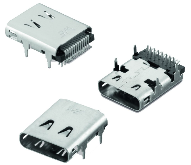
Wurth ElektronikUSB-C now offers different connector variants ranging from USB 2.0 in Type-C housing to Type-C for a 10 GBit data rate. The housing variants have also become more diverse. From the horizontal hybrid type to vertical variants and the mid-mount type, which is placed in a PCB cutout. All these types have their special characteristics, which in many cases may already have to be taken into account in the layout to ensure problem-free manufacturing is possible afterwards. We would like to shed light on these points and identify ways of dealing with the challenges. The PCB itself and its manufacture cannot be left out of the equation either, as it has certain limitations that should be taken into account in order to achieve the best possible result. Once all this has been done, it is a matter of controlling the manufacturing process in its various steps from stencil printing to the soldering oven and optimizing the parameters, so that the slender type-C connectors can also be processed in a way suitable for series production.
LED - Application Guide
Wurth ElektronikDuring the automatic pick and place process, the influence of mechanical stress on the surface must be minimized as much as possible. LEDs with a silicone resin provide many advantages. Compared to other reflector areas of Surface Mount LEDs, silicone is generally softer. Due to this fact, the handling area of the nozzle should only contact the Plastic Leaded Chip Carrier (PLLC) surface directly and is not allowed to touch the silicone encapsulation of the component.
