
LTM4619EV Demo Board | µModule Regulator with Tracking, 4.5V ≤ VIN ≤ 28V, VOUT1 = 3.3V @ 4A, VOUT2 = 1.8V @ 4A
Analog Devices Inc.Demonstration circuit 1453A features the LTM4619EV, a 4.5V to 28V input, high efficiency, high density, dual 4A step-down power module with 1.8V and 3.3V output voltages. Derating is necessary for certain VIN, VOUT, and thermal conditions. The two outputs are interleaved with 180° phase to minimize the input ripple and reduce the input capacitors. A minimum design only requires the bulk input and output capacitors and voltage setting resistors. The LTM4619EV features output voltage tracking, power good indicator, RUN pin control, clock synchronization and soft-start programming. Protection features include foldback current limiting and overvoltage protection. Burst Mode® operation or pulse skipping mode can be selected for better light load efficiency.

DC1461A
Analog Devices Inc.The LTC3616 is a low quiescent current monolithic synchronous buck regulator using a current mode, constant frequency architecture. The no-load DC supply current in sleep mode is only 70?A while maintaining the output voltage (Burst Mode operation) at no load, dropping to zero current in shutdown. The 2.25V to 5.5V input supply voltage range makes the LTC3616 ideally suited for single Li-Ion as well as fixed low voltage input applications. 100% duty cycle capability provides low dropout operation, extending the operating time in battery-powered systems.The operating frequency is externally programmable up to 4MHz, allowing the use of small surface mount inductors. For switching noise-sensitive applications, the LTC3616 can be synchronized to an external clock at up to 4MHz.Forced continuous mode operation in the LTC3616 reduces noise and RF interference. Adjustable compensation allows the transient response to be optimized over a wide range of loads and output capacitors.The internal synchronous switch increases efficiency and eliminates the need for an external catch diode, saving external components and board space. The LTC3616 is offered in a leadless 24-pin 3mm ? 5mm thermally enhanced QFN package.Applications Point-of-Load Supplies Distributed Power Supplies Portable Computer Systems DDR Memory Termination Handheld Devices

LTM4618EV Demo Board | µModule Regulator, 4.5V ≤ VIN ≤ 26.5V, VOUT = Programmable 1.2V to 5V @ 6A
Analog Devices Inc.Demonstration circuit 1472 features the LTM4618EV μModule® regulator, a complete high efficiency synchronous buck regulator with tracking. The DC1472 input range is from 4.5V to 26.5V and is capable of delivering up to 6A of output current; however, current derating may be necessary under certain VIN, VOUT, frequency and thermal conditions. The output voltage is jumper programmable from 1.2V to 5V and can be set as low as 0.8V, the reference voltage of the LTM4618EV.

LT3980EMSE Demo Board | 6.8V ≤ VIN ≤ 58V (80V Transients), VOUT = 5V @ 2A
Analog Devices Inc.Demonstration circuit 1476A is a 2A, 58V step-down switching regulator with 75µA quiescent current featuring the LT3980EMSE. The demo board is designed for a 5V/2A output from a 6.8V to 58V input with transients up to 80V.

LTC2634-HMI12: 12-Bit VOUT Quad DAC (4.096V Reference, Reset to Mid-scale, Internal Reference), (Requires DC590)
Analog Devices Inc.DC1488A-D: Demo Board for the LTC2634-12 Quad 12-Rail-to-Rail DACs with 10ppm/°C Reference.

LTC3619EDD Demo Board | 5V Input, VOUT1 = 3.3V @ 400mA, VOUT2 = 3.4V @ 500mA (2A Pulsed)
Analog Devices Inc.Demonstration circuit 1489A is a synchronous buck dual regulator with adjustable input current limit featuring the LTC3619EDD(Burst mode operation)/LTC3619BEDD(pulse-skip mode) and is ideally suited for pulsed load applications where the input current needs to be limited. The -A board is for the LTC3619 while the -B board is for the LTC3619B. It is configured for 500mA maximum input current limit. The outputs are configured for a 3.3V/400mA continuous current output and a 3.4V output that can handle pulsed load currents up to 2A, with duty cycles up to 15%. The input voltage range is 5V ±10%. The fixed input current limited can be adjusted by replacing one resistor.

LT2940 | Power and Current Monitor
Analog Devices Inc.DC1495A: Demo Board for the LT2940 Power and Current Monitor.

DC1496C-C
Analog Devices Inc.The LTC2941-1 measures battery charge state in battery-powered handheld PC and portable product applications. Its operating range is perfectly suited for single cell Li-Ion batteries. A precision coulomb counter integrates current through an internal sense resistor between the battery?s positive terminal and the load or charger. The measured charge is stored in internal registers. An SMBus/I2C interface accesses and configures the device.The LTC2941-1 features programmable high and low thresholds for accumulated charge. If a threshold is exceeded, the device communicates an alert using either the SMBus alert protocol or by setting a flag in the internal status register. Integrated Sense Resistor LTC2941 No LTC2941-1 Yes Applications Low Power Handheld Products Cellular Phones MP3 Player Cameras GPS

DC1496C-D
Analog Devices Inc.The LTC2942-1 measures battery charge state, battery voltage and chip temperature in handheld PC and portable product applications. Its operating range is perfectly suited for single cell Li-Ion batteries. A precision coulomb counter integrates current through an internal sense resistor between the battery?s positive terminal and the load or charger. Battery voltage and on-chip temperature are measured with an internal 14-bit No Latency ??? ADC. The three measured quantities (charge, voltage and temperature) are stored in internal registers accessible via the onboard SMBus/I2C interface.The LTC2942-1 features programmable high and low thresholds for all three measured quantities. If a programmed threshold is exceeded, the device communicates an alert using either the SMBus alert protocol or by setting a flag in the internal status register. Integrated Sense Resistor LTC2942 No LTC2942-1 Yes Applications Low Power Handheld Products Cellular Phones MP3 Players Cameras GPS

DC1497A
Analog Devices Inc.The LT3597 is a 60V triple step-down LED driver capable of achieving 10,000:1 digital PWM dimming at 100Hz with fast NPN current sources driving up to 10 LEDs in each channel. LED dimming can also be achieved via analog control of the CTRL1-3 pin.The step-down switching frequency is programmed between 200kHz and 1MHz. The frequency is also synchronizable to an external clock. The LT3597 provides maximum LED brightness while adhering to manufacturers? specifications for thermal derating. The derate temperature is programmed by placing a negative temperature coefficient (NTC) resistor on the master control pin.The LT3597 adaptively controls VOUT in order to achieve optimal efficiency. Other features include: 2% LED current matching between channels, open LED reporting, shorted LED protection, programmable LED current, and programmable temperature protection.Applications LED Billboards and Signboards Mono, Multi, Full-Color LED Displays Large Screen Display LED Backlighting Automotive, Industrial, and Medical Displays

DC1508B-A
Analog Devices Inc.The LTC2977 is an 8-channel Power System Manager used to sequence, trim (servo), margin, supervise, manage faults, provide telemetry and create fault logs. PMBus commands support power supply sequencing, precision point-of-load voltage adjustment and margining. DACs use a proprietary soft-connect algorithm to minimize supply disturbances. Supervisory functions include overvoltage and undervoltage threshold limits for eight power supply output channels and one power supply input channel, as well as over and under temperature limits. Programmable fault responses can disable the power supplies with optional retry after a fault is detected. Faults that disable a power supply can automatically trigger black box EEPROM storage of fault status and associated telemetry. An internal 16-bit ADC monitors eight output voltages, one input voltage, and die temperature. In addition, odd numbered channels can be configured to measure the voltage across a current sense resistor. A programmable watchdog timer monitors microprocessor activity for a stalled condition and resets the microprocessor if necessary. A single wire bus synchronizes power supplies across multiple LTC Power System Management (PSM) devices. Configuration EEPROM with ECC supports autonomous operation without additional software.APPLICATIONS Computers and Network Servers Industrial Test and Measurement High Reliability Systems Medical Imaging Video

DC1508B-B
Analog Devices Inc.The LTC2975 is a 4-channel Power System Manager used to sequence, trim (servo), margin, supervise, manage faults, provide telemetry and create fault logs. PMBus commands support power supply sequencing, precision point-of-load voltage adjustment and margining. DACs use a proprietary soft-connect algorithm to minimize supply disturbances. Supervisory functions include over and under current, voltage and temperature threshold limits for four power supply output channels as well as over and under voltage threshold limits for a single power supply input channel. Programmable fault responses can disable the power supplies with optional retry after a fault is detected. Faults that disable a power supply can automatically trigger black box EEPROM storage of fault status and associated telemetry. An internal 16-bit ADC monitors four output voltages, four output currents, four external temperatures, input voltage and current, and die temperature. Input power, energy, and output power is also calculated. A programmable watchdog timer monitors microprocessor activity for a stalled condition and resets the microprocessor if necessary. A single wire bus synchronizes power supplies across multiple ADI Power System Management (PSM) devices. Configuration EEPROM with ECC supports autonomous operation without additional software.APPLICATIONS Computers and Network Servers Industrial Test and Measurement High Reliability Systems Video and Medical Imaging

DC150B-A
Analog Devices Inc.The LTC1067/LTC1067-50 consist of two identical rail-to-rail, high accuracy and very wide dynamic range 2nd order switched-capacitor building blocks. Each building block, together with three to five resistors, provides 2nd order filter functions such as bandpass, highpass, lowpass, notch and allpass. High precision 4th order filters are easily designed. The center frequency of each 2nd order section is tuned by the external clock frequency. The internal clock-to-center frequency ratio (100:1 for the LTC1067 and 50:1 for the LTC1067-50) can be modified by the external resistors. These devices have a double sampled architecture which places aliasing and imaging components at twice the clock frequency. The LTC1067-50 is a low power device consuming about one half the current of the LTC1067. The LTC1067-50?s typical supply current is about 1mA from a 3.3V supply. The LTC1067 and LTC1067-50 are available in 16-pin narrow SSOP and SO packages. Mask programmable versions of the LTC1067 and LTC1067-50, with thin film resistors on-chip and custom clock-to-cutoff frequency ratios, can be designed in an SO-8 package to realize application specific monolithic filters. Please contact LTC Marketing for more details.Applications Notch Filters Narrowband Bandpass Filters Tone Detection Noise Reduction Systems

LTC3858EUH Demo Board | Dual, 2-Phase, 16V ≤ VIN ≤ 26V, VOUT = 12V @ 25A
Analog Devices Inc.Demonstration circuit 1510A is a high output voltage, high efficiency synchronous poly-phase buck converter featuring the LTC3858EUH. The demo circuit is available in two versions. The input voltage of both versions is 16V to 26V. DC1510A-A is configured using 2 LTC3858's with 4 phase interleaving operation which provides a 12V/50A output, while the DC1510A-B is configured with 1 LTC3858 with 2 phase inter-leaving operation which provides a 12V/25A output.
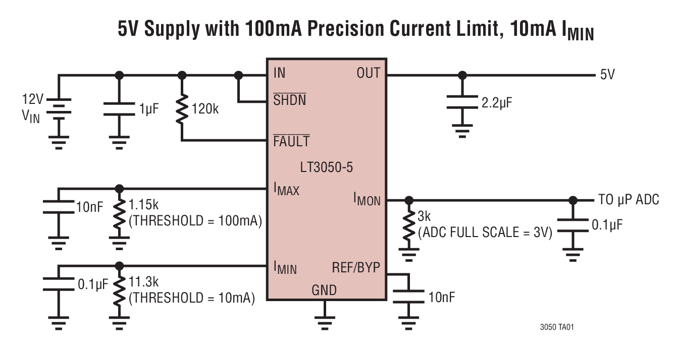
LT3050EDDB Demo Board | Micropower Low Noise, Low Dropout Linear Regulator, Current Limit, Diagnostics, 2V ≤ VIN ≤ 45V, VOUT = 1.2V/1.5V/1.8V/2.5V/3.3V/5V/Adjustable at 100mA
Analog Devices Inc.Demonstration circuit 1515 is an adjustable 100mA linear regulator featuring the LT3050. The LT3050 is a micropower, low noise and low dropout voltage linear regulator. The device supplies 100mA of output current with a dropout voltage of 340mV. A 10nF bypass capacitor reduces output noise to 30μVRMS (10Hz to 100kHz bandwidth) and soft-starts the reference. The demo board's 2V to 45V input voltage range combined with its precision current limit and diagnostic functions make the IC an ideal choice for robust, high reliability applications such as protected antenna power supplies. The jumper-selectable output voltage can be set to 1.2V, 1.5V, 1.8V, 2.5V, 3.3V, 5V or a user-defined voltage. The input and output pins can withstand up to ±50V and the output is short-circuit protected.
The internal current limit should be considered when the input-to-output differential is high. The LT3050's current limit can be programmed by a single resistor and is accurate to ±5% over a wide input voltage and temperature range. A single resistor programs the LT3050’s minimum output current monitor, useful for detecting open-circuit conditions. The current monitor function sources a current equal to 1/100th of output current. A logic FAULT pin asserts low if the LT3050 is in current limit, operating below its minimum output current (open-circuit) or is in thermal shutdown.

LTC2267-12 | 12-Bit, 105Msps, 1.8V Dual Serial ADC, 5MHz < AIN < 170MHz, Requires DC1371 and DC1075
Analog Devices Inc.DC1532A-H: Demo Board for the LTC2267-12 12-Bit, 105Msps Low Power Dual ADCs.
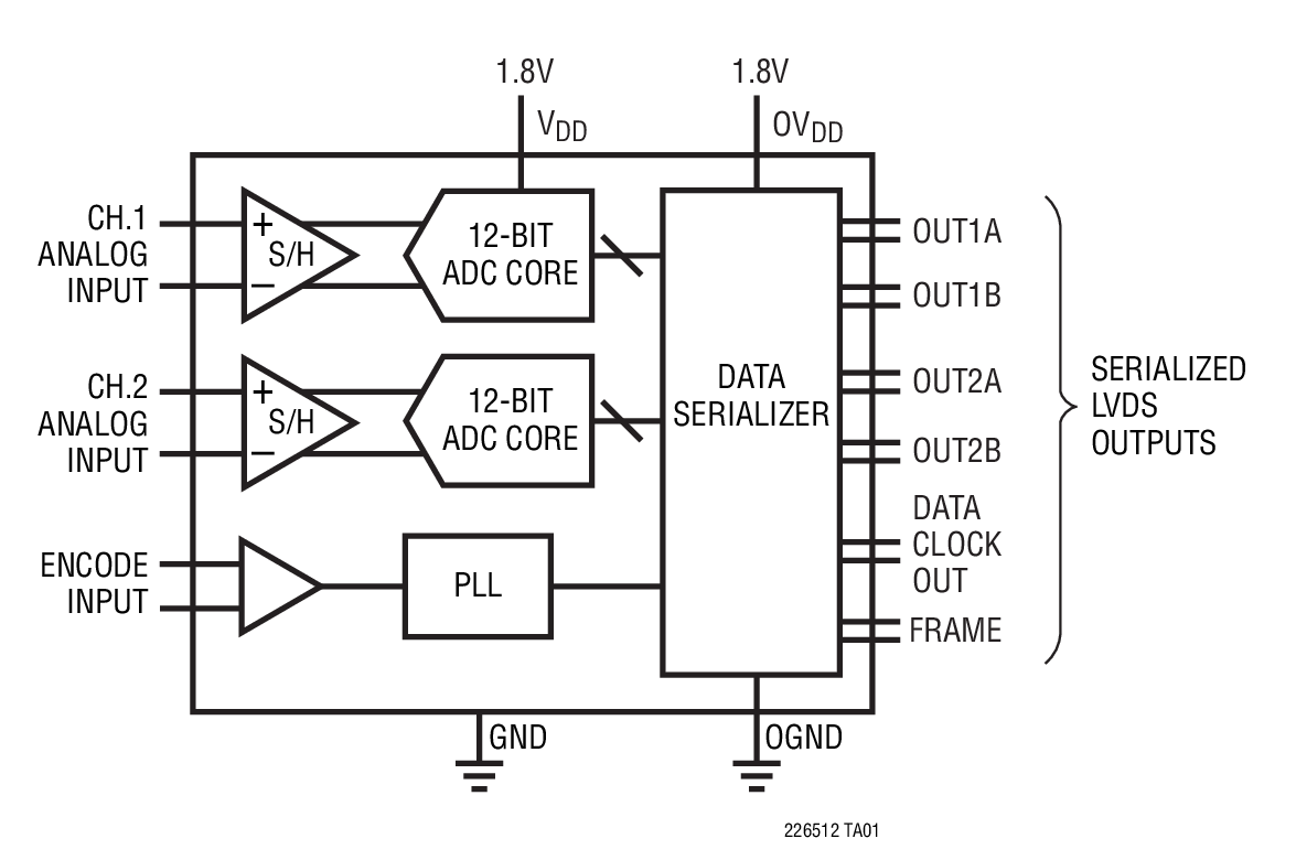
LTC2263-12 | 12-Bit, 25Msps, 1.8V Dual Serial ADC, 5MHz < AIN < 170MHz, Requires DC1371 and DC1075
Analog Devices Inc.DC1532A-L: Demo Board for the LTC2263-12 12-Bit, 25Msps Low Power Dual ADCs.

LTC2637-HZ12 | 12-Bit Octal I2C DAC (4.096V Internal Reference Mode, Reset to Zero-Scale), Requires DC590
Analog Devices Inc.DC1534A-C: Demo Board for the LTC2637-12 Octal 12-Bit I2C VOUT DACs with 10ppm/°C Reference.

LTC6102-1 Current Sense Demo Board with Enable Feature
Analog Devices Inc.DC1536A: Demo Board for the LTC6102 Precision Zero Drift Current Sense Amplifier.

LT3992EFE Demo Board | Dual Buck with Tracking, 7V ≤ VIN ≤ 60V, VOUT1 = 5V @ 2A, VOUT2 = 3.3V @ 2A
Analog Devices Inc.The demo circuit 1537A is a dual current mode PWM step-down DC/DC converter featuring LT3992. The demo circuit is designed for 5V and 3.3V outputs from a 7V to 60V input. The current capability of each channel is up to 3A when running individually and 2A when both are sourcing the same current without special heat sinking. Individual soft-start, current limit, comparator, input voltage for each output as well as frequency division and synchronous and clock output functions simplify the complex design of dual-output power converters.


