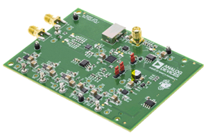
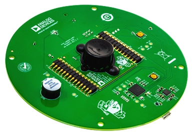
LTC3440EMS Demo Board (MSOP)| 1MHz, Synchronous Buck-Boost, VIN = 2.5V to 5.5V, VOUT = 3.3V @ 0.6A
Analog Devices Inc.Demonstration Circuit 425B is a constant-frequency synchronous Buck-Boost converter using the LTC3440. The input range is from 2.5V to 5.5V, making it ideal for single-cell lithium-ion or three-cell NiCd/NiMH battery applications. For 2.7V minimum input voltage, this converter can provide up to 600mA load current. The output voltage is set at 3.3V. A different output voltage in the range of 2.5V to 5.5V can be obtained by changing one of the feedback resistors.

LTC3731CG | 3-Phase, VIN = 9V to 14V, VOUT = 2.5V/1.8V @ 60A
Analog Devices Inc.Demonstration circuit 438 is a triple phase, single output synchronous buck converter featuring the LTC3731CG. This circuit can be used for desktop computers and servers, notebook computers and other high output current DC/DC converters. The output voltage can be configured for either 2.5V or 1.8V and the maximum load current is 60A. The input voltage range of DC438 is 9V to 14V.

LTC3728EUH | 2-Phase Dual Output Power Supply, VIN = 5V - 14V, VOUT1 = 2.5V @ 13A, VOUT2 = 1.8V @ 13A
Analog Devices Inc.Demonstration circuit 447 is a step-down converter featuring the LTC3728EUH regulator. The PolyPhase® dual output controller LTC3728EUH drives two high current synchronous buck converters. Input is 5V–14V, output 1 is 2.5V with loads up to 13A and output 2 is 1.8V with loads up to 13A. For applications with input voltage less than 5V, DC447 includes a circuit footprint on the bottom side to provide a 5V bias power supply.

LTC3717EGN | DDR, HSTL, STTL Termination Power Supply, 5V-20VIN, VREF/2 @ 12A
Analog Devices Inc.DC450A: Demo Board for LTC3717 Wide Operating Range, No RSENSE Step-Down Controller for DDR/QDR Memory Termination.

DC469A
Analog Devices Inc.The LTC3830/LTC3830-1 are high power, high efficiency switching regulator controllers optimized for 3.3V-5V to 1.xV-3.xV step-down applications. A precision internal reference and feedback system provide ?1% output regulation over temperature, load current and line voltage variations. The LTC3830/LTC3830-1 use a synchronous switching architecture with N-channel MOSFETs. Additionally, the chip senses output current through the drain-source resistance of the upper N-channel FET, providing an adjustable current limit without a current sense resistor.The LTC3830/LTC3830-1 operate with an input supply voltage as low as 3V and with a maximum duty cycle of >91% over temperature. They include a fixed frequency PWM oscillator for low output ripple operation. The 200kHz free-running clock frequency can be externally adjusted or synchronized with an external signal from 100kHz to 500kHz. In shutdown mode, the LTC3830 supply current drops to

LTC3405AES6 | ThinSOT Synchronous Buck Regulator, 2.5 to 5.5 VIN, Adjustable (1.2V) VOUT @ 300mA(3.0 VIN min), (High Efficiency Inductor)
Analog Devices Inc.DC480A-F: Demo Board for the LTC3405A 1.5MHz, 300mA Synchronous Step-Down Regulator in ThinSOT.

LTC1760CFW Demo Board | Dual Li-Ion Smart Battery Charger, VIN = 12V to 20V, Charge Current = 4A Max.
Analog Devices Inc.Demonstration circuit 486B is a dual Smart Battery PowerPath and charger controller featuring the LTC1760. The input voltage is 12 to 20V. The charger output voltage is programmed SMBus serial interface. The maximum charge current is 4A. The demo board has been optimized to work with 2, 3 and 4- Cell Li-ion battery packs. A jumper is provided to select trip for low battery voltage (LOBAT), VLIMIT (VLIM), and ILIMIT (ILIM). The LTC1760 follows the Smart Battery Standards for the Smart Battery System Manager (SBSM) specification.

LTC3406ES5 Demo Board | 2.7V to 5.5VIN, 1.2VOUT @ 600mA(Max)
Analog Devices Inc.Demonstration circuit DC500 is a constant-frequency step-down converter, using the various versions (fixed output/adjustable output/Burst Mode/Burst Mode defeated) of the LTC3406 or LTC3406B monolithic synchronous buck regulators. The DC500 has an input voltage range of 2.7V to 5.5V, and is capable of delivering up to 600 mA of output current at minimum input voltage of 3V. The DC500A-A features the adjustable output, Burst Mode-capable LTC3406 with the output voltage set to 1.2V.

LTC3703EGN Demo board | High Input Voltage, Step-Down 6A Power Supply, 20 to 72VIN, 12VOUT @ 6A
Analog Devices Inc.Demonstration circuit 501 is high power, high voltage, and high efficiency DC/DC buck converter featuring the LTC3703. This is a general-purpose high voltage DC to DC with an input voltage range of 20V to 72V. The board is optimized for positive 48V input operation with high voltage surges up to 72VDC allowed. The limiting factor is the LTC3703 GN16 package that will not meet UL/CSA/IEC60950 clearance and creepage distance requirements above the SELV 60VDC maximum due to pin spacing. If the user wishes to support higher continuous input voltages or compliance to 60950, the LTC3703 is offered in a G-28 pin package. See Data Sheet. However, for the purposes of evaluation, the board will work reliably up to 72V. The maximum continuous current in free air is 4A. 6A is permissible with some forced air cooling. The output voltage is programmed with a voltage divider and configured for 12V.

LT1725CGN | Low Cost, High Efficiency Synchronous Forward Converter without Optoisolator, +VIN = 36V to 72V, +VOUT = 2.5V/3.3V at 10A
Analog Devices Inc.DC508A: Demo Board for the LT1725 General Purpose Isolated Flyback Controller.

LTC4100EG | 3-/4-Cell Li-Ion Smart Battery Charger, DCIN = 15V to 20V, up to 4A Charge Current, (Requires DC1223)
Analog Devices Inc.Demonstration circuit DC512B is a single battery switching step-down charge controller featuring the LTC4100. The recommended input power is 15 to 20V at 3.5A. A two-position jumper allows choice of protected output voltage range suitable for 3- and 4-Cell Li-ion batteries. Removal of the jumper allows full output voltage range. The maximum charge current is 4A.
The demo board is initially configured for 12.6V at 3A for popular 3-cell Li-ion battery packs. LTC4100 will automatically charge a Smart Battery to termination as soon as input power is applied with a battery connected prior to power up. A VOUT pin automatically provides power to the system load from the wall adapter or battery. Status LEDs are provided for CHG, ACP, SMBALERT and SMBus activity.

LTC3423EMS Demo Board | 1V ≤ VIN ≤ 1.6V, VOUT = 1.8V @ 350mA
Analog Devices Inc.Demonstration circuit 516A-A is a low output voltage, synchronous boost converter featuring the LTC3423. The LTC3423 is ideal for applications that require an output voltage between 1.5V to 2.6V from a single alkaline or NiCd/NiMH cell. A bias voltage (VDD) of 2.7V to 5.5V is required to power the internal circuitry. The input voltage (VIN) range is 1V to 1.6V, but once up and running, the device can operate with an input voltage as low as 0.5V. The output voltage is set at 1.8V. For a 1V minimum battery voltage, the LTC3423 can provide 350mA.

DC531A-A
Analog Devices Inc.The LTC4052 is a complete standalone pulse charger with integrated MOSFET for 1-cell lithium-ion batteries.An external sense resistor provides overcurrent limiting as a safety precaution against a user connecting a wall adapter with the incorrect or no current limit. The internal MOSFET prevents reverse battery current from flowing if the input voltage is shorted to ground, eliminating the need for a blocking diode.As the battery accepts charge and approaches the programmed float voltage, the internal MOSFET begins switching off and on with the duty cycle gradually decreasing as the battery approaches a fully charged condition. A programmable timer terminates the charge cycle. The near end-of-charge C/10 condition is indicated at the CHRG pin when the average charge current falls to one tenth of the wall adapter current. Removing the input voltage puts the LTC4052 into a sleep mode, dropping the battery current drain to less than 1?A.The LTC4052 is available in a tiny 8-pin thermally enhanced MSOP package.Applications Handheld Computers Cellular Telephones Cradle Chargers

LT3436EFE Demo Board | 3.2V ≤ VIN ≤ to 12V, VOUT = 12V @ up to 2A
Analog Devices Inc.Demonstration circuit 533 is an 800kHz adjustable output boost regulator featuring the LT3436. This current-mode control monolithic (switch included) converter has a wide operating supply voltage of 3V to 25V and a minimum peak switch current rating of 3A, though the demo board has a reduced input voltage range of 3.2V to 12V. It provides 12V at 550mA from a 3.3V input and 12V at 900mA from a 5V input.

LT3150CGN Demo Board | Low Voltage LDO Linear Regulator Controller, 1.1V ≤ VIN ≤ 10V, VOUT = 1.2V/1.5/1.8V @ 4A
Analog Devices Inc.Demonstration circuit 534 is a fast transient response, very low dropout linear regulator featuring the 4A output current LT3150 linear regulator controller. The DC534 has an input voltage range of 1.1V to 10V and generates a jumper-selectable output voltage of 1.2V, 1.5V or 1.8V.
With the LT3150 driving external N-channel MOSFETs as source followers, the DC534 can produce very fast transient response. The proper selection of the Rds(on) of the MOSFETs allows dropout voltages below 300 mV. These capabilities, plus its ability to maintain stable operation with ceramic output capacitors, make the DC534 voltage regulator ideally suited for low VIN-to-VOUT applications, such as microprocessor/microcontroller/FPGA power supplies.

LTC4211 Hot Swap Controller (20A version)
Analog Devices Inc.DC536A-B: Demo Board for the LTC4211 Hot Swap Controller with Multifunction Current Control.
LTC4211CMS Demo Board | 7A Electronic Circuit Breaker and Hot Swap Controller
Analog Devices Inc.Demonstration circuit 536B is a hot swap controller with multifunction current control featuring the LTC4211. The DC536B-A is configured to operate with up to 7A load and DC536B-B up to 20A load.

LTC5509ESC6 | 3GHz RF Power Detector (No Gain Compression)
Analog Devices Inc.The DC539B demo board is used to evaluate the LTC5509, RF power detector with integrated output buffer and voltage reference. The LTC5509 converts an RF input signal at pin 6 (RF) to a DC voltage at pin 3 (VOUT). The RF input frequency range is 300 MHz to 3000 MHz. Maximum input power is 8 dBm. The output voltage at VOUT will start at an initial DC value of typically 250mV. When the RF signal is applied the output voltage will increase.
LTC3728EG | Dual 2-Phase, 8V to 24V Input, 5V/3.3V 0A to 12A, 3.3V/2.5V 0A to 12A
Analog Devices Inc.Demonstration circuit 542 is a dual output, dual phase synchronous step-down controller, featuring the LTC3728EG. Output #1 can be configured for either 5.0V or 3.3V and output #2 can be configured for either 3.3V or 2.5V. The maximum load for both rails is 12A. The input voltage range of the DC542 is 8V to 24V. The DC542 also contains a footprint for a 5.5V boost converter bias supply whose output is connected to EXTVCC. See the “Optional Bias Supply” section for more details.

LTC4002EDD-8.4 | Li-Ion Battery Charger with Charge Termination, +VIN = 9.3V to 24V, 3A Charge Current
Analog Devices Inc.DC551A-B: Demo Board for the LTC4002-4.2 Standalone Li-Ion Switch Mode Battery Charger.