EVAL-AD5063EBZ
Analog Devices Inc.The AD5063, a member of the Analog Device Inc., nanoDAC? family, is a low power, single 16-bit, unbuffered voltage-output DAC that operates from a single 2.7 V to 5 V supply. The device offers a relative accuracy specification of ?1 LSB, and operation is guaranteed monotonic with a ?1 LSB DNL specification. The AD5063 comes with on-board resistors in a 10-lead MSOP, allowing bipolar signals to be generated with an output amplifier. The device uses a versatile 3-wire serial interface that operates at clock rates up to 30 MHz and that is compatible with standard SPI?, QSPI?, MICROWIRE?, and DSP interface standards. The reference for the AD5063 is supplied from an external VREF pin. A reference buffer is also provided on-chip. The device incorporates a power-on reset circuit that ensures the DAC output powers up to midscale and remains there until a valid write to the device takes place. The device contains a power-down feature that reduces the current consumption of the device to typically 300 nA at 5 V and provides software-selectable output loads while in power-down mode. The device is put into power-down mode via the serial interface. Total unadjusted error for the device is

AD5110 Evaluation Board
Analog Devices Inc.The Evaluation board for the AD5110 contains a SDP connection and software which allows the AD5110 to be controlled from an SDP board.
This evaluation board requires an SDP Controller board for connection to the PC. The SDP controller board connects to the PC via USB 2.0. The evaluation board will connect to the SDP controller board. The evaluation board cannot be connected directly to the PC. The evaluation software running on the PC will communicate with the evaluation board through the SDP Controller board.
The SDP Controller board is a separate list item in the ordering guide below (EVAL-SDP-CS1Z). If you have not previously purchased an SDP Controller board, please do so to ensure a full evaluation setup.

EVAL-AD5111SDZ
Analog Devices Inc.The AD5111 provides a nonvolatile solution for 128-position adjustment applications, offering guaranteed low resistor tolerance errors of ?8% and up to ?6 mA current density in the A, B, and W pins. The low resistor tolerance, low nominal temperature coefficient, and high bandwidth simplifyopen-loop applications, as well as tolerance matching applications.The new low wiper resistance feature minimizes the wiper resistance in the extremes of the resistor array to only 45 ? typical.A simple 3-wire up/down interface allows manual switching or high speed digital control with clock rates up to 50 MHz.The AD5111 is available in a 2 mm ? 2 mm LFCSP package. The parts are guaranteed to operate over the extended industrial temperature range of ?40?C to +125?C.APPLICATIONS Mechanical potentiometer replacement Portable electronics level adjustment Audio volume control Low resolution DAC LCD panel brightness and contrast control Programmable voltage to current conversion Programmable filters, delays, time constants Feedback resistor programmable power supply Sensor calibration

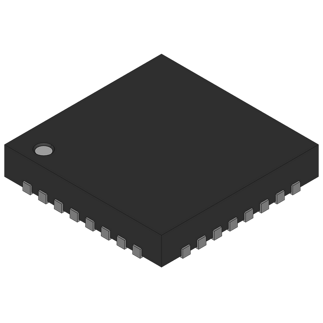
EVAL-AD5144DBZ
Analog Devices Inc.The AD5124/AD5144/AD5144A potentiometers provide a nonvolatile solution for 128-/256-position adjustment applications, offering guaranteed low resistor tolerance errors of ?8% and up to ?6 mA current density in the Ax, Bx, and Wx pins.The low resistor tolerance and low nominal temperature coefficientsimplify open-loop applications as well as applications requiringtolerance matching.The linear gain setting mode allows independent programmingof the resistance between the digital potentiometer terminals, through the RAW and RWB string resistors, allowing very accurate resistor matching.The high bandwidth and low total harmonic distortion (THD)ensure optimal performance for ac signals, making these devicessuitable for filter design.The low wiper resistance of only 40 ? at the ends of the resistor array allow for pin-to-pin connection.The wiper values can be set through an SPI-/I2C-compatible digital interface that is also used to read back the wiper register andEEPROM contents.The AD5124/AD5144/AD5144A are available in a compact, 24-lead, 4 mm ? 4 mm LFCSP and a 20-lead TSSOP. The partsare guaranteed to operate over the extended industrial temperaturerange of ?40?C to +125?C.APPLICATIONS Portable electronics level adjustment LCD panel brightness and contrast controls Programmable filters, delays, and time constants Programmable power suppliesThe AD5144-EP supports defense and aerospace applications (AQEC).

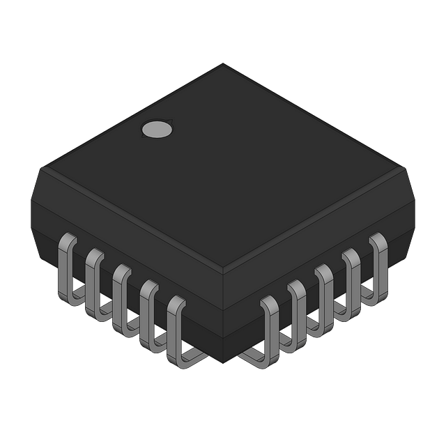
EVAL-AD5161DBZ
Analog Devices Inc.The AD5161 provides a compact 3 mm ? 4.9 mm packagedsolution for 256-position adjustment applications. Thesedevices perform the same electronic adjustment function asmechanical potentiometers or variable resistors, with enhancedresolution, solid-state reliability, and superior low temperaturecoefficient performance.The wiper settings are controllable through a pin selectable SPIor I2C compatible digital interface, which can also be used toread back the wiper register content. When the SPI mode isused, the device can be daisy-chained (SDO to SDI), allowingseveral parts to share the same control lines. In the I2C mode, address pin AD0 can be used to place up to two devices on thesame bus. In this same mode, command bits are available toreset the wiper position to midscale or to shut down the deviceinto a state of zero power consumption.Operating from a 2.7 V to 5.5 V power supply and consumingless than 5 ?A allows for usage in portable battery-operatedapplications.APPLICATIONS Mechanical potentiometer replacement in new designs Transducer adjustment of pressure, temperature, position, chemical, and optical sensors RF amplifier biasing Gain control and offset adjustment?

EVAL-AD5162SDZ
Analog Devices Inc.The AD5162 provides a compact 3 mm נ4.9 mm packaged solution for dual 256 position adjustment applications. This device performs the same electronic adjustment function as a 3-terminal mechanical potentiometer.Available in four different end-to-end resistance values (2.5 k?, 10 k?, 50 k?, 100 k?), this low temperature coefficient device is ideal for high accuracy and stability-variable resistance adjustments.The wiper settings are controllable through the SPI compatible digital interface. The resistance between the wiper and either end point of the fixed resistor varies linearly with respect to the digital code transferred into the RDAC latch.Operating from a 2.7 V to 5.5 V power supply and consuming less than 6 ?A allows the AD5162 to be used in portable battery-operated applications.For applications that program the AD5162 at the factory, Analog Devices offers device programming software running on Windows? NT/2000/XP operating systems. This software effectively replaces the need for external SPI controllers, which in turn enhances the time to market of systems. An AD5162 evaluation kit and software are available. The kit includes a cable and instruction manual.APPLICATIONS Systems calibrations Electronics level settings Mechanical trimmers replacement in new designs Permanent factory PCB setting Transducer adjustment of pressure, temperature, position, chemical, and optical sensors RF amplifier biasing Automotive electronics adjustment Gain control and offset adjustment

EVAL-AD5165DBZ
Analog Devices Inc.The AD5165 provides a compact 2.9 mm ? 2.8 mm packaged solution for 256-position adjustment applications. These devices perform the same electronic adjustment function as mechanical potentiometers or variable resistors, with enhanced resolution, solid-state reliability, and superior low temperature coefficient performance. The AD5165?s supply voltage requirement is 2.7 V to 5.5 V, but its logic voltage requirement is 1.8 V to VDD. The AD5165 consumes very low quiescent power during standby mode and is ideal for battery-operated applications.Wiper settings are controlled through a simple 3-wire interface. The interface is similar to the SPI? digital interface except for the inverted chip-select function that minimizes logic power consumption in the idling state. The resistance between the wiper and either endpoint of the fixed resistor varies linearly with respect to the digital code transferred into the wiper register.Operating from a 2.7 V to 5.5 V power supply and consuming less than 50 nA typical standby power allows use in battery-operated portable or remote utility device applications.Note: The terms digital potentiometer, RDAC, and VR are used interchangeably.APPLICATIONS Battery-operated electronics adjustment Remote utilities meter adjustment Mechanical potentiometer replacement Transducer circuit adjustment Automotive electronics adjustment Gain control and offset adjustment System calibration VCXO adjustment

EVAL-AD5228DBZ
Analog Devices Inc.The AD5228 is Analog Devices? latest 32-step-up/step-down control digital potentiometer emulating mechanical potentiometer operation. Its simple up/down control interface allows manual control with just two external pushbutton tactile switches. The AD5228 is designed with a built-in adaptive debouncer that ignores invalid bounces due to contact bounce commonly found in mechanical switches. The debouncer is adaptive, accommodating a variety of pushbutton tactile switches that generally have less than 10 ms of bounce time during contact closures. When choosing the switch, the user should consult the timing specification of the switch to ensure its suitability in an AD5228 application.The AD5228 can increment or decrement the resistance in discrete steps or in autoscan mode. When the PU or PD button is pressed briefly (no longer than 0.6 s), the resistance of the AD5228 changes by one step. When the PU or PD button is held continuously for more than a second, the device activates the autoscan mode and changes four resistance steps per second.The AD5228 can also be controlled digitally; its up/down features simplify microcontroller usage. The AD5228 is available in a compact thin SOT-23-8 (TSOT-8) package. The part is guaranteed to operate over the automotive temperature range of ?40?C to +105?C.The AD5228?s simple interface, small footprint, and very low cost enable it to replace mechanical potentiometers and trimmers with typically 3? improved resolution, solid-state reliability, and faster adjustment, resulting in considerable cost saving in end users? systems.Users who consider EEMEM potentiometers should refer to the recommendations in the Applications section.APPLICATIONS Mechanical potentiometer and trimmer replacements LCD backlight, contrast, and brightness controls Digital volume control Portable device-level adjustments Electronic front panel-level controls Programmable power supply

EVAL-AD5233SDZ
Analog Devices Inc.The AD5233 is a quad-channel nonvolatile memory,1 digitally controlled potentiometer2 with a 64-step resolution. The device performs the same electronic adjustment function as a mechanical potentiometer with enhanced resolution, solid-state reliability, and remote controllability. The AD5233 has versatile programming using a serial peripheral interface (SPI) for 16 modes of operation and adjustment, including scratchpad programming, memory storing and restoring, increment/decrement, ?6 dB/step log taper adjustment, wiper setting readback, and extra EEMEM for user-defined information such as memory data for other components, look-up tables, or system identification information.In the scratchpad programming mode, a specific setting can be programmed directly to the RDAC register, which sets the resistance between Terminal W to Terminal A and Terminal W to Terminal B. This setting can be stored into the EEMEM and is transferred automatically to the RDAC register during system power-on.The EEMEM content can be restored dynamically or through external PR strobing. A WP function protects EEMEM contents. To simplify the programming, independent or simultaneous increment or decrement commands can be used to move the RDAC wiper up or down, one step at a time. For logarithmic ?6 dB step changes in wiper settings, the left or right bit shift command can be used to double or halve the RDAC wiper setting.The AD5233 is available in a thin 24-lead TSSOP package. The part is guaranteed to operate over the extended industrial temperature range of ?40?C to +85?C.APPLICATIONS Mechanical potentiometer replacement Instrumentation: gain, offset adjustment Programmable voltage-to-current conversion Programmable filters, delays, time constants Programmable power supply Sensor calibration

EVAL-AD5235SDZ
Analog Devices Inc.The AD5235 is a dual-channel, nonvolatile memory, digitallycontrolled potentiometer with 1024-step resolution, offeringguaranteed maximum low resistor tolerance error of ?8%.The device performs the same electronic adjustment functionas a mechanical potentiometer with enhanced resolution, solidstate reliability, and superior low temperature coefficient performance.The versatile programming of the AD5235 via anSPI?-compatible serial interface allows 16 modes of operationand adjustment including scratchpad programming, memorystoring and restoring, increment/decrement, ?6 dB/step log taperadjustment, wiper setting readback, and extra EEMEM for user-definedinformation such as memory data for other components,look-up table, or system identification information.In the scratchpad programming mode, a specific setting canbe programmed directly to the RDAC register, which sets theresistance between Terminal W and Terminal A and Terminal Wand Terminal B. This setting can be stored into the EEMEMand is restored automatically to the RDAC register duringsystem power-on.The EEMEM content can be restored dynamically or throughexternal PR strobing, and a WP function protects EEMEMcontents. To simplify the programming, the independent orsimultaneous linear-step increment or decrement commandscan be used to move the RDAC wiper up or down, one step ata time. For logarithmic ?6 dB changes in the wiper setting, theleft or right bit shift command can be used to double or halve theRDAC wiper setting.The AD5235 patterned resistance tolerance is stored in theEEMEM. The actual end-to-end resistance can, therefore, beknown by the host processor in readback mode. The host canexecute the appropriate resistance step through a softwareroutine that simplifies open-loop applications as well asprecision calibration and tolerance matching applications.The AD5235 is available in a thin, 16-lead TSSOP package.The part is guaranteed to operate over the extended industrialtemperature range of ?40?C to +85?C.Applications DWDM laser diode driver, optical supervisory systems Mechanical potentiometer replacement Instrumentation: gain, offset adjustment Programmable voltage-to-current conversion Programmable filters, delays, time constants Programmable power supply Low resolution DAC replacement Sensor calibration

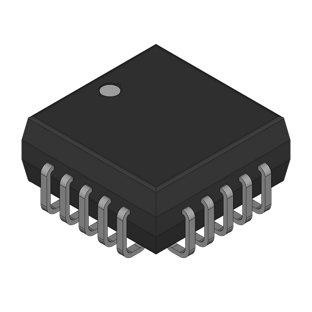
EVAL-AD5258DBZ
Analog Devices Inc.The AD5258 provides a compact, nonvolatile 3 mm ? 4.9 mm packaged solution for 64-position adjustment applications. These devices perform the same electronic adjustment function as mechanical potentiometers?or variable resistors, but with enhanced resolution and solid-state reliability.The wiper settings are controllable through an I2C-compatible digital interface that is also used to read back the wiper register and EEPROM content in addition, resistor tolerance is stored within EEPROM, providing an end-to-end tolerance accuracy of 0.1%. There is also a software write protection function that ensures data cannot be written to the EEPROM register.A separate VLOGIC pin delivers increased interface flexibility. For users who need multiple parts on one bus, Address Bit AD0 and Address Bit AD1 allow up to four devices on the same bus.APPLICATIONS LCD panel VCOM adjustment LCD panel brightness and contrast control Mechanical potentiometer replacement in new designs Programmable power supplies RF amplifier biasing Automotive electronics adjustment Gain control and offset adjustment Fiber to the home systems Electronics level settings

EVAL-AD5270SDZ
Analog Devices Inc.The AD5270 /?AD5271 are single-channel, 1024-/256-position digital rheostats that combine industry leading variable resistor performance with nonvolatile memory (NVM) in a compact package.The AD5270 / AD5271 ensure less than 1% end-to-end resistor tolerance error and offer 50-times programmable (50-TP) memory.The guaranteed industry leading low resistor tolerance error feature simplifies open-loop applications as well as precision calibration and tolerance matching applications.The AD5270 / AD5271 device wiper settings are controllable through the SPI digital interface. Unlimited adjustments are allowed before programming the resistance value into the 50-TP memory. The AD5270/AD5271 do not require any external voltage supply to facilitate fuse blow and there are 50 opportunities for permanent programming. During 50-TP activation, a permanent blow fuse command freezes the resistance position (analogous to placing epoxy on a mechanical trimmer).The AD5270 / AD5271 are available in a 3 mm x 3 mm, 10-lead LFCSP package and in a 10-lead MSOP package. The parts are guaranteed to operate over the extended industrial temperature range of ?40?C to +125?C.APPLICATIONS Mechanical potentiometer replacements Op-amp: variable gain control Instrumentation: gain, offset adjustment Programmable voltage-to-current conversions Programmable filters, delays, time constants Programmable power supply Sensor calibration

EVAL-AD5311RDBZ
Analog Devices Inc.The AD5310R?/ AD5311R, members of the nanoDAC? family, are low power, single-channel, 10-bit buffered voltage-out DACs. The devices include a 2.5 V, 2 ppm/?C internal reference. The output span can be programmed to be 0 V to VREF or 0 V to 2 ? VREF. All devices operate from a single 2.7 V to 5.5 V supply and are guaranteed monotonic by design. The devices are available in 10-lead MSOP packages.The AD5310R / AD5311R also incorporate a power-on resetcircuit that ensures that the DAC output powers up to zeroscaleand remains there until a valid write takes place. Thedevice contains a power-down feature that reduces the currentconsumption of the device to 2 ?A at 5 V while in power-downmode.The AD5310R / AD5311R use a versatile SPI or I2C interface,including an asynchronous RESET pin and a VLOGIC pin, allowing 1.8 V compatibility.PRODUCT HIGHLIGHTS High Relative Accuracy (INL): ?0.5 LSB maximum. Low Drift 2.5 V On-Chip Reference: 5 ppm/?C maximum temperature coefficient.APPLICATIONS Process controls Data acquisition systems Digital gain and offset adjustment Programmable voltage sources Optical modules

EVAL-AD7705EBZ
Analog Devices Inc.The AD7705 / AD7706?are complete analog front ends for low frequency measurement applications. These 2-/3-channel devices can accept low level input signals directly from a transducer and produce serial digital output. The devices employ a ?-? conversion technique to realize up to 16 bits of no missing codes performance. The selected input signal is applied to a proprietary, programmable-gain front end based around an analog modulator. The modulator output is processed by an on-chip digital filter. The first notch of this digital filter can be programmed via an on-chip control register, allowing adjustment of the filter cutoff and output update rate. The AD7705 / AD7706 devices operate from a single 2.7 V to 3.3 V or 4.75 V to 5.25 V supply. The AD7705 features two fully differential analog input channels; the AD7706 features three pseudo differential input channels. Both devices feature a differential reference input. Input signal ranges of 0 mV to 20 mV through 0 V to 2.5 V can be incorporated on both devices when operating with a VDD of 5 V and a reference of 2.5 V. They can also handle bipolar input signal ranges of ?20 mV through ?2.5 V, which are referenced to the AIN(?) inputs on the AD7705 and to the COMMON input on the AD7706.The AD7705 / AD7706 devices, with a 3 V supply and a 1.225 V reference, can handle unipolar input signal ranges of 0 mV to 10 mV through 0 V to 1.225 V. The devices can accept bipolar input ranges of ?10 mV through ?1.225 V. Therefore, the AD7705 / AD7706 devices perform all signal conditioning and conversion for a 2-channel or 3-channel system. The AD7705 / AD7706 are ideal for use in smart, microcontroller, or DSP-based systems. The devices feature a serial interface that can be configured for 3-wire operation. Gain settings, signal polarity, and update rate selection can be configured in software using the input serial port. The parts contains self-calibration and system calibration options to eliminate gain and offset errors on the part itself or in the system. CMOS construction ensures very low power dissipation, and the power-down mode reduces the standby power consumption to 20 ?W typ. These parts are available in a 16-lead, wide body (0.3 inch), plastic dual in-line package (DIP); a 16-lead, wide body (0.3 inch), standard small outline (SOIC) package; and a low profile, 16-lead, thin shrink small outline package (TSSOP).