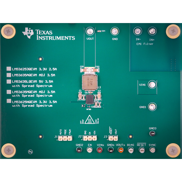
LM53635M-Q1 3.5A 5.0V Adjustable Output 2.1MHz Automotive Step-Down Converter With Spread Spectrum
Texas InstrumentsLM53635M-Q1 3.5A 5.0V Adjustable Output 2.1MHz Automotive Step-Down Converter With Spread Spectrum
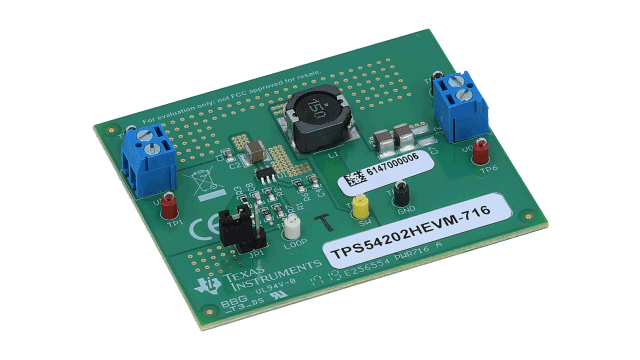
TPS54202H 2A Output; Synchronous Step-Down Converter Evaluation Module
Texas InstrumentsTPS54202H 2A Output; Synchronous Step-Down Converter Evaluation Module
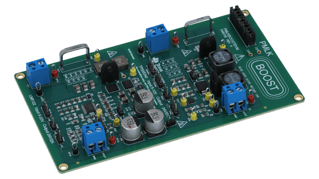
TI-PMLK Boost Experiment Board using TPS55340 & LM5122
Texas InstrumentsTI-PMLK Boost Experiment Board using TPS55340 & LM5122
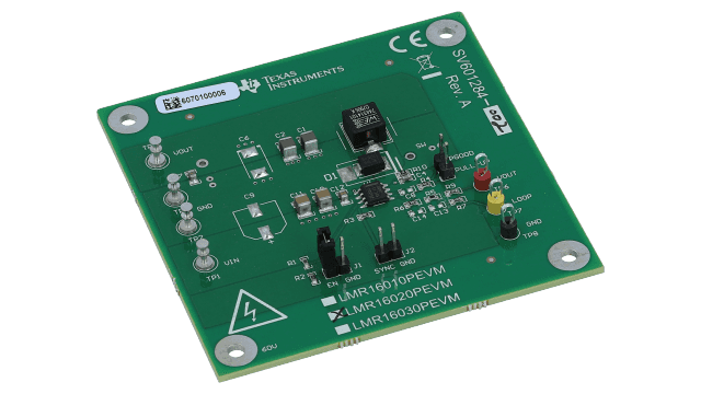
LMR16020 Wide Vin Step-Down Converter Evaluation Module
Texas InstrumentsLMR16020 Wide Vin Step-Down Converter Evaluation Module
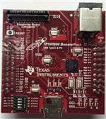
TPS65986 USB Type-C & USB PD Controller & Power Switch Evaluation Module
Texas InstrumentsTPS65986 USB Type-C & USB PD Controller & Power Switch Evaluation Module
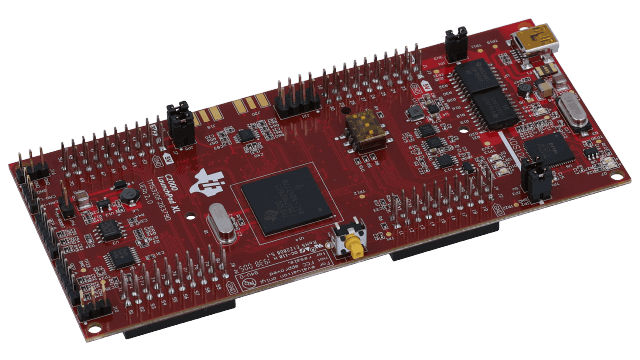
F28379D LaunchPad™ development kit for C2000™ Delfino™ MCU
Texas InstrumentsF28379D LaunchPad™ development kit for C2000™ Delfino™ MCU
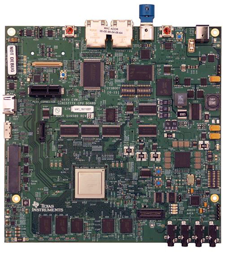
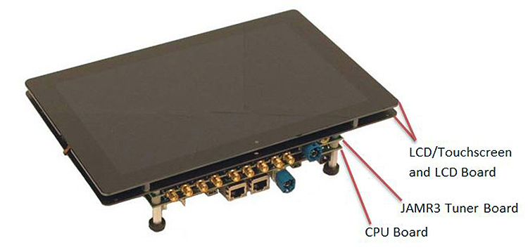
TDA2x Vision EVM Kit – Spectrum Digital (Includes CPU Board and Vision Application Board)
Texas InstrumentsTDA2x Vision EVM Kit – Spectrum Digital (Includes CPU Board and Vision Application Board)
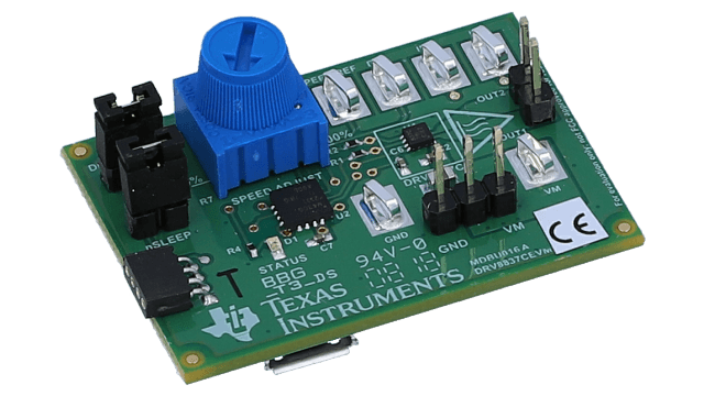
1-A Low-Voltage H-Bridge Evaluation Module
Texas Instruments1-A Low-Voltage H-Bridge Evaluation Module
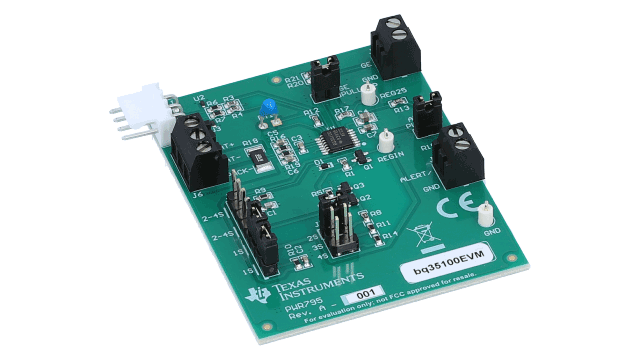
bq35100 Lithium Primary Cell Evaluation Module Using End-of-Service Monitor Gas Gauging
Texas Instrumentsbq35100 Lithium Primary Cell Evaluation Module Using End-of-Service Monitor Gas Gauging
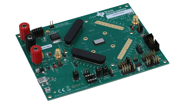
28 Gbps multi-rate 8-channel retimer evaluation module
Texas Instruments28 Gbps multi-rate 8-channel retimer evaluation module
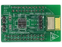
CYBLE-214009-EVAL
Cypress SemiconductorDevelopment Board for EZ-BLE PSoC Module (CYBLE-214009-00) Applications
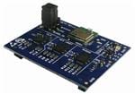
EVAL_PAN1322
Panasonic Industrial DevicesEvaluation Board for PAN1322 Bluetooth Module BT2.1 Class 2 Application w/Ant.
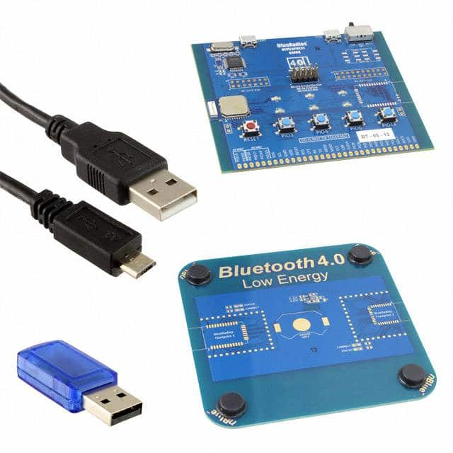
EVAL_PAN1721BR
Panasonic Industrial DevicesPAN1721 Evaluation Kit (ENW-89835A3KF) with BlueRadios Software
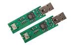
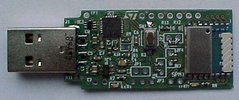
EVAL_PAN1740
Panasonic Industrial DevicesEvaluation kit for BLE Bluetooth Low Energy Module Dialog DA14580
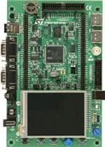
STM32100E-EVAL
STMicroelectronicsEvaluation Board for ARM Cortex-M3 Core-based STM32F100 Microcontroller
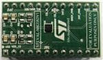
STEVAL-MKI163V1
STMicroelectronicsLSM303C 3 Axis Sensor Adapter Evaluation Board for Standard DIL24 Socket