MAXREFDES1275
Description
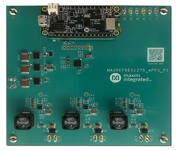
1A,3-Channel LED Driver in Buck Configuration using MAX20050 and its dimming control using MAX32630FTHR
The MAXREFDES1275 has three main blocks: the microcontroller, ADC/DAC IC MAX11311, and three LED drivers. The brightness of each LED string can be set by applying an industry standard 0V to 10V dimming signal. The LED brightness should scale linearly to this signal. A conversion is required as the range and offset of the analog DIM input on the LED driver is different from this 0V to 10V signal. The microcontroller manages this by sampling the 0V to 10V DIM signals with the ADCs, calculating the new values, and forwarding them as analog voltages to the LED drivers with the DACs. A PC can be connected for a calibration procedure as the offset and maximum current can vary between the channels. The new constants are stored in the flash memory after calibration.
Features
- Active low-fault (FLT) indicator
- Output short-circuit protection
- High-side current regulation eliminates one connection to the LED string
- 5V, 10mA LDO output provides bias to other circuits
- Ultra-low shutdown current (5μA typ)
Applications
Product Categories
| Part Number | Name | Companion Part | |
|---|---|---|---|
| MAX17632AATE+ | MAX17632AATE+ | Buy Datasheet | |
| MAX17632BATE+ | MAX17632BATE+ | Buy Datasheet | |
| MAX17632CATE+ | MAX17632CATE+ | Buy Datasheet |
| Title | Updated | Type | Size (KB) | |
|---|---|---|---|---|
| Circuit Note | ||||
| Overview of Reference Design |