
Search results
ADP2139CB-0.8EVALZ

Analog Devices Inc.
ADP2139CB-0.8EVALZ
Analog Devices Inc.
The ADP2138 and ADP2139 are high efficiency, low quiescent current, synchronous step-down dc-to-dc converters. The ADP2139 has the additional feature of an internal discharge switch. The total solution requires only three tiny external components. When the MODE pin is set high, the buck regulator operates in forced PWM mode, which provides low peak-to-peak ripple for power supply noise sensitive loads at the expense of light load efficiency. When the MODE pin is set low, the buck regulator automatically switches operating modes, depending on the load current level. At higher output loads, the buck regulator operates in PWM mode. When the load current falls below a predefined threshold, the regulator operates in power save mode (PSM), improving light load efficiency.The ADP2138/ADP2139 operate on input voltages of 2.3 V to 5.5 V, which allows for single lithium or lithium polymer cell, multiple alkaline or NiMH cell, PCMCIA, USB, and other standard power sources. The maximum load current of 800 mA is achievable across the input voltage range.The ADP2138/ADP2139 are available in fixed output voltages of 3.3 V, 3.0 V, 2.8 V, 2.5 V, 1.8 V, 1.5 V, 1.2 V, 1.0 V, and 0.8 V. All versions include an internal power switch and synchronous rectifier for minimal external part count and high efficiency. The ADP2138/ADP2139 have internal soft start and they are internally compensated. During logic controlled shutdown, the input is disconnected from the output and the ADP2138/ADP2139 draw 0.2 ?A (typical) from the input source.Other key features include undervoltage lockout to prevent deep battery discharge, and soft start to prevent input current overshoot at startup. The ADP2138/ADP2139 are available in a 6-ball wafer level chip scale package (WLCSP).Applications PDAs and palmtop computers Wireless handsets Digital audio, portable media players Digital cameras, GPS navigation units
ADL5317-EVALZ

Analog Devices Inc.
ADL5317-EVALZ
Analog Devices Inc.
The ADL5317 is a high-voltage, wide dynamic range biasing and current monitoring device optimized for use with avalanche photodiodes. With the provision of a stable high-voltage supply up to 80 V, the bias voltage at the VAPD pin can be varied from 6 V to 75 V using the 3 V compatible VSET pin. The current sourced from the VAPD pin, over a range of 5 nA to 5 mA, is accurately mirrored with an attenuation of 5 and sourced from the IPDM monitor output. In a typical application, the monitor output drives a current-input logarithmic amplifier to produce an output representing the optical power incident upon the photodiode. The photodiode anode may be connected to a high-speed transimpedance amplifier for the extraction of the data stream.A signal of 0.2 V to 2.5 V with respect to ground applied at the VSET pin is amplified by a fixed gain of 30 to produce the 6 V to 75 V bias at Pin VAPD. The accuracy of the bias control interface of the ADL5317 allows for straightforward calibration, thereby maintaining a constant avalanche multiplication factor of the photodiode over temperature. The current monitor output, IPDM, maintains its high linearity vs. photodiode current over the full?range of APD bias voltage. The current ratio of 5:1 remains constant as VSET and VPHV are varied.The ADL5317 also offers a supply tracking mode compatible with adjustable high voltage supplies. The VAPD pin accurately follows 2.0 V below the VPHV supply pin when VSET is tied to a voltage from 3.0 V to 5.5 V (or higher with a current limiting resistor), and the VCLH pin is open.Protection from excessive input current at VAPD as well as excessive die temperature is provided. The voltage at VAPD falls rapidly from its setpoint when the input current exceeds 18 mA nominally. A die temperature in excess of 140?C will cause the bias controller and monitor to shut down until the temperature falls below 120?C. Either overstress condition will trigger a logic low at the FALT pin, an open collector output loaded by an external pull-up to an appropriate logic supply (1 mA max).The ADL5317 is available in a 16-lead LFCSP package and is specified for operation from ?40?C to +85?C.APPLICATIONS Optical power monitoring and biasing in APD systems Wide dynamic range voltage sourcing and current monitoring in high voltage systems
Universal AC input 5V1A Charger

Texas Instruments
Universal AC input 5V1A Charger
Texas Instruments
This reference design demostrates a low cost single PCB solution for 5V1A cube charger. By using primary side regulation (PSR) mode chip UCC28700: < 30-mW No-Load power is achieved: which meets 5-star rating. The overall size is limited in 22mm(L)X21mm(W)x20mm(H).
6V to 20V Synchronous Buck Controller with Sync and Power Good

Texas Instruments
6V to 20V Synchronous Buck Controller with Sync and Power Good
Texas Instruments
The design implements a TPS40195. The TPS40195 is a flexible synchronous buck controller that operates from a nominal 4.5 V to 20 V supply. This controller implements voltage mode control with the switching frequency adjustable from 100 kHz to 600 kHz. Flexible features found on this device include
Non-Dimmable LED Lighting Driver Controller (38V@350mA)
Texas Instruments
Non-Dimmable LED Lighting Driver Controller (38V@350mA)
Texas Instruments
The PMP6001 reference design is an isolated (flyback) non-dimmable LED Lighting Driver Controller using the TPS92210. This reference design accepts an universal input voltage (90V - 265V). The output voltage is set to 38V and the LED string current to set to 350mA
ADP1051DC1-EVALZ

Analog Devices Inc.
ADP1051DC1-EVALZ
Analog Devices Inc.
The ADP1051 is an advanced digital controller with a PMBus? interface targeting high density, high efficiency dc-to-dc power conversion. This controller implements voltage mode control with high speed, input line feedforward for enhanced transient and improved noise performance. The ADP1051 has six programmable pulse-width modulation (PWM) outputs capable of controlling most high efficiency power supply topologies, with added control of synchronous rectification (SR). The device includes adaptive dead time compensation to improve efficiency over the load range, and programmable light load mode operation, combined with low power consumption, to reduce system standby power losses.The ADP1051 implements several features to enable a robust system of parallel and redundant operation for customers that require high availability or parallel connection. The device provides synchronization, reverse current protection, pre-bias startup, accurate current sharing between power supplies, and conditional overvoltage techniques to identify and safely shut down an erroneous power supply in parallel operation mode.The ADP1051 implements several features to enable a robust system of parallel and redundant operation for customers that require high availability or parallel connection. The device provides synchronization, reverse current protection, pre-bias startup, accurate current sharing between power supplies, and conditional overvoltage techniques to identify and safely shut down an erroneous power supply in parallel operation mode.APPLICATIONS High density, isolated DC/DC power supplies Intermediate bus converters High availability parallel power systems Server, storage, industrial, networking, and communications infrastructure
DC1893A
Analog Devices Inc.
DC1893A
Analog Devices Inc.
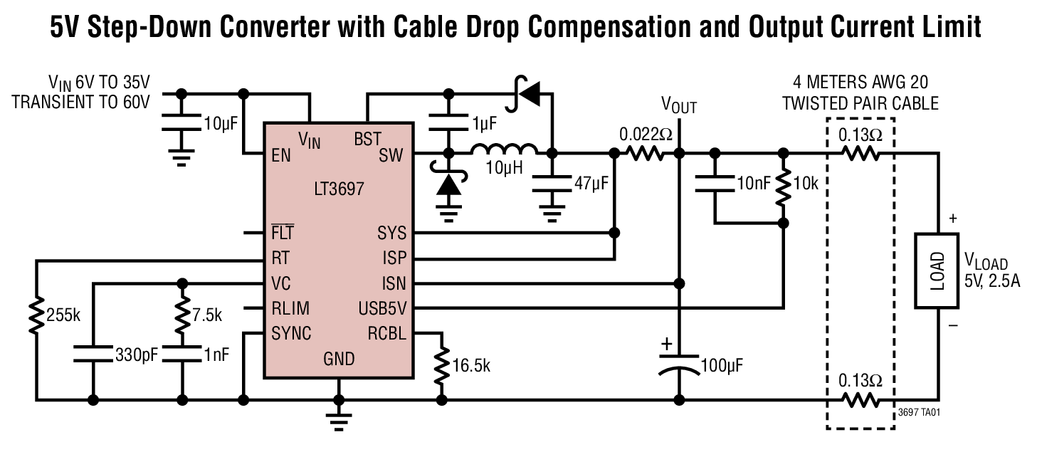
The LT3697 is a 35V, 2.5A step-down switching regulator designed to power 5V USB applications. A precise output voltage and programmable cable drop compensation maintain accurate 5V regulation at the USB socket connected to the end of a long cable. The accurate, programmable current limit can eliminate the need for a USB power switch and improve system reliability. The provided 180mA active load reduces output overshoot during load transients. Dual feedback allows regulation on the output of a USB switch and limits cable drop compensation to a maximum of 6.1V output, protecting USB devices during fault conditions. A separate 5V output can be taken from the SYS terminal to power auxiliary circuitry such as a USB hub controller. The LT3697 also provides a load current monitor output and an overcurrent fault indicator.The LT3697 operates from 300kHz to 2.2MHz and withstands input voltage transients up to 60V. The device's output survives shorts to ground and to the battery. A current mode topology is used for fast transient response and good loop stability. Shutdown reduces input supply current to less than 1?A. The LT3697 is available in a 16-lead MSOP package with an exposed pad for low thermal resistance.Applications Automotive USB Industrial USB
LTC3639EMSE Demo Board | Sync Buck, 4V ≤ VIN ≤ 150V, VOUT = 1.8V/3.3V/5V/Adj @ 100mA
Analog Devices Inc.
LTC3639EMSE Demo Board | Sync Buck, 4V ≤ VIN ≤ 150V, VOUT = 1.8V/3.3V/5V/Adj @ 100mA
Analog Devices Inc.
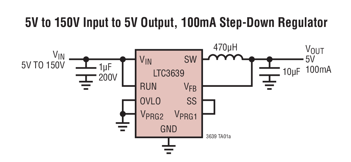
Demonstration circuit 1901A is a 150V input, 100mA output DC/DC power supply featuring the LTC3639. The IC operates in a high efficiency Burst Mode® operation and includes internal high and low side power MOSFETs. The board will accept an input voltage between 4V and 150V, and provide jumper selected output voltages of 1.8V, 3.3V, 5V and an option for additional voltages. The IC includes internal soft-start and a provision for increasing soft-start time.
AD-MRLIDAR1-EBZ
Analog Devices Inc.
AD-MRLIDAR1-EBZ
Analog Devices Inc.
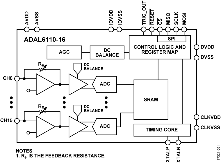
The ADAL6110-16 is a light detection and ranging (LIDAR)signal processor IC that supports simultaneous capture of up to16 channels. Each channel is integrated with a 16-bit analog todigital converter (ADC) to measure the optical return signal.The ADAL6110-16 stores the captured waveforms to staticrandom access memory (SRAM) storage. The data outputreadout and functional configuration of the LIDAR signalprocessor occurs over a 4-wire serial port interface (SPI).The LIDAR signal processor features a dc balance control toreject signal offset and corruption due to modulated interference,eliminating the need for external dc cancellation circuitry. Inaddition, the LIDAR signal processor has a built-in automaticgain control (AGC) that modifies the gain of the system toensure the signal of interest is automatically scaled to themeasurement range.The ADAL6110-16 simplifies the traditional multichannelLIDAR system implementation by integrating the transimpedanceamplifier (TIA), gain and sampling stages, as well as providingthe transmitter fire signal, all of which are managed by on-chipcontrol logic. No external components are required between thephotodiodes and the TIA interface of each channel in theLIDAR signal processor.Applications Autonomous systems collision avoidance Corridor mapping Dynamic suspension and flight control Drone altitude monitoring Industrial distance measurement Mounted safety curtain systems Parking spot monitoring Blind spot detection
EVAL-AD7980SDZ

Analog Devices Inc.
EVAL-AD7980SDZ
Analog Devices Inc.
The AD7980 is a 16-bit, successive approximation, analog-to-digital converter (ADC) that operates from a single power supply, VDD. It contains a low power, high speed, 16-bit sampling ADC and a versatile serial interface port. On the CNV rising edge, it samples an analog input IN+ between 0 V to REF with respect to a ground sense IN?. The reference voltage, REF, is applied externally and can be set independent of the supply voltage, VDD. Its power scales linearly with throughput.The SPI-compatible serial interface also features the ability, using the SDI input, to daisy-chain several ADCs on a single, 3-wire bus and provides an optional busy indicator. It is compatible with 1.8 V, 2.5 V, 3 V, or 5 V logic, using the separate supply VIO.The AD7980 is housed in a 10-lead MSOP or a 10-lead QFN (LFCSP) with operation specified from ?40?C to +125?C.APPLICATIONSAutomated test equipmentData acquisition systemsMedical instrumentsMachine automation

85VAC-265VAC Input: 12V/15W Output Green-Mode Flyback

Texas Instruments
85VAC-265VAC Input: 12V/15W Output Green-Mode Flyback
Texas Instruments
The PMP6833 reference design uses the UCC28600 green-mode controller to generate a 12V/15W regulated output. The quasi-resonant switching of the UCC28600 allows this low-cost design to achieve a maximum load efficiency is over 83%: while the no load losses are less than 200mW.
LTC3535EDD Demo Board | Dual Channel 550mA 1MHz Synchronous Step-Up DC/DC Converter

Analog Devices Inc.
LTC3535EDD Demo Board | Dual Channel 550mA 1MHz Synchronous Step-Up DC/DC Converter
Analog Devices Inc.
DC1483A: Demo Board for the LTC3535 Dual Channel 550mA 1MHz Synchronous Step-Up DC/DC Converter.